Xlr3 Wiring Diagram
Xlr3 Wiring Diagram - Cable designed for being cut into standard mic cables may have 2 pairs of wire and a shield around the outside in that case pair the colors together and make sure they go to the same pin number on each end. A wiring diagram is a straightforward visual representation of the physical connections and physical layout of the electrical system or circuit. Be sure to always ground to the shell to avoid hum. Any interference that penetrates the overall braided screen affects both the hot and. Here is the basic wiring diagram for a standard 3 pin xlr connector used in audio for mics playback machines intercom etc. Pin 2 on the xlr is hot and carries the positive going signal whilst pin 3 is cold and provides the return. Xlr3 Wiring Diagram Each component ought to be placed and linked to different parts in specific way. The rear view is the end you solder from here are the connections on each pin.
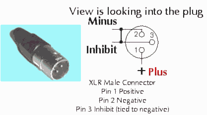
Xlr3 Wiring Diagram - Xlr wiring diagram pdf xlr cable wiring diagram pdf xlr wiring diagram pdf every electrical structure is composed of various distinct parts. A balanced system is used in pro audio systems xlr wiring diagram shown below with an overall screen covering a twisted pair. If not the structure will not function as it should be. The above diagram shows you the pin numbering for both male and female xlr connectors from the front and the rear view.
Related Posts of Xlr3 Wiring Diagram :

Xlr Wiring Diagram Pdf Diagram Base Website Diagram Pdf

Wiring Configuration For An Xlr To Ew Plug 3 5 Mm Sennheiser

3 Pin Xlr Connector Pinout Diagram Pinouts Ru

Amphenol To Xlr 4 Pin Wiring Diagram Diagram Base Website Wiring

Xlr 3 Pin Wiring Diagram Diagram Base Website Wiring Diagram

Charging Cable For Wheel Chairs And Electric Bicycles That Use The
17+ Pictures Xlr3 Wiring Diagram
Xlr3 wiring diagram - 3 pin xlr wiring standard 3 pin xlr connectors are standard amongst line level and mic level audio applications. I normally drill a hole inside the shell and attach a ring terminal with three ground wires one to the element one to the pot and one to the connector. When and how to use a wiring diagram.
It shows the way the electrical wires are interconnected and will also show where fixtures and components may be attached to the system. Volume pot wiring diagram if you want the pot to turn in the opposite direction pins 1 and 3 can be reversed. Use wiring diagrams to.
3 5 mm jack to xlr wiring diagram wiring diagram is a simplified all right pictorial representation of an electrical circuit it shows the components of the circuit as simplified shapes and the faculty and signal connections between the devices.
Gallery of Xlr3 Wiring Diagram :

How To Wire An Xlr Cannon Audio Plug For Unbalanced Line

Balanced Cables

Making The Wrong Cable Work For You

Mb 0485 Wiring Diagram 1 4 Stereo Jack On Stereo Headphone Jack

Diagram 2012 Ta Stereo Wiring Diagram Full Version Hd Quality

82w82b 3 Way Switch Wiring 1 4 Quot Trs Wiring Diagram Hd Quality

Random Contributions Using Unshielded Ethernet Cat5 Cat5e Cat6

Naim System Connection Help Pink Fish Media

2 79 20cm Stereo 3 5mm 1 8 Male To Xlr 3 Pin Male Jack

10set Mini Xlr 3 4 5 6 Pin Female Plug Male Socket Small Xlr Audio

Hosa Dmx 106 5 Pin Male Xlr To 3 Pin Female Xlr Dmx 512 Adaptor

Ta4f Mini Xlr To 3 5mm Adapter Gearslutz
Xlr3 Wiring Diagram - 3 5 mm jack to xlr wiring diagram wiring diagram is a simplified all right pictorial representation of an electrical circuit it shows the components of the circuit as simplified shapes and the faculty and signal connections between the devices. Use wiring diagrams to. Volume pot wiring diagram if you want the pot to turn in the opposite direction pins 1 and 3 can be reversed. It shows the way the electrical wires are interconnected and will also show where fixtures and components may be attached to the system.
