4 Wire Pt100 Wiring Diagram
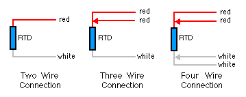
4 Wire Pt100 Wiring Diagram - A pt1000 measuring element in class a also offers good measurement accuracies in a 2 wire connection and represents an economical alternative to 3 or 4 wire connections for machine building. Pt100 wiring methods 2 3 or 4 wire. There are 2 wiring methods for the rtd module and pt100 temperature sensors two wire and three wire connections. 4 wire rtd circuits not only cancel lead wires but remove the effects of mismatched resistances such as contact points. Rtd wiring configurations there are three types of wire configurations 2 wire 3 wire and 4 wire that are commonly used in rtd sensing circuits. Is drives a precise measuring current through l1 and l4. 4 Wire Pt100 Wiring Diagram A common version is the constant current circuit shown here. Idac generates the sensor excitation and the reference voltage.
4 Wire Pt100 Wiring Diagram - 2 3 4 wire rdt pt100 to pt1000 temperature measurement. The wiring of a pt100 temperature is different to other temperature sensors in particular thermocouples it is important to get the wiring of your sensor correct otherwise the measuring instrument may give an incorrect reading or no reading at all. Read the next few paragraphs for rtd type configuration selection for your application or skip to the bottom for wiring diagrams. The highest measurement accuracies are only achievable with a pt100 in a 4 wire connection.
Related Posts of 4 Wire Pt100 Wiring Diagram :
20+ Pictures 4 Wire Pt100 Wiring Diagram

4 wire pt100 wiring diagram - Voltage drop across the line resistance are compensated. Put another way if you buy a pt100 board you can use it to read 2 3 or 4 wire rtds by simply adding or subtracting jumper wires between input terminals on the board. L2 and l3 measure the voltage drop across the rtd element.
Is drives a precise measuring current through l1 and l4. L2 and l3 measure the voltage drop across the rtd element. Connect the black or white lead on the negative side for the resistive.
4 wire rtd circuits not only cancel lead wires but remove the effects of mismatched resistances such as contact points. A1b1 a2b2 and c1c2. 2 wire rtd connections the 2 wire rtd configuration is the simplest among rtd circuit designs.
A common version is the constant current circuit shown here. 4 wire rtd signal connection connect each of the red leads on the positive side of the resistive element to the excitation positive and channel positive on the daq device. Noise and drift of the ref voltage are correlated and therefore canceled.
A 2 wire configuration with a compensating loop is also an option. The following connection diagrams illustrate how to connect various rtd types to your daq device. When wiring with two wires first jumper across a1 and b1and a2 and b2 respectively then connect pt100 sensors and to the rtd module according to the following diagram on the left.
Gallery of 4 Wire Pt100 Wiring Diagram :
4 Wire Pt100 Wiring Diagram - When wiring with two wires first jumper across a1 and b1and a2 and b2 respectively then connect pt100 sensors and to the rtd module according to the following diagram on the left. The following connection diagrams illustrate how to connect various rtd types to your daq device. A 2 wire configuration with a compensating loop is also an option. Noise and drift of the ref voltage are correlated and therefore canceled.


